|
Building a Kansas National Guard M1A1
by Scott Conner
Once in a while, you get lucky. I got lucky twice. One is Fine Scale Modeler
came out with an article on building an M1A2 in the July 2001 issue before
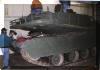
I had finished mine. Another one is I had the opportunity to visit an actual
M1A1 several times thanks to Gary Owsley, a fellow armor builder and Kansas
National Guard member. The intent of this article is to augment the Fine Scale
article, not to tear it apart. I know every tank is different, and I am not
claiming to be an expert on M1’s, and I am not saying Mr. George Kolasa is wrong
in his article, but there are some details on the M1 kept at the Kansas National
Guard Armory that Mr. Kolasa does not have on his model. That is what I would
like to share with you.


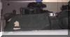
My model was built "ready for action." That meant removing the smoke
discharge covers, muzzle cover, and mounting the two machine guns. What is the
point of modeling a tank sitting in a garage?
The kit I used was the Dragon M1A2, backdated to the M1A1. All the parts are
there, so nothing new was needed. Gary showed me the differences and what was
needed to backdate this model. The only problem was the commander’s machine gun.
On the A2, they have different machine gun, The A1’s is in the kit, but not in
the instructions. I chose this kit over the Tamiya for the texture of the
non-skid surfaces (and the price), but in the kit I got, the upper hull was
badly warped. I grabbed some spare, square brass tubing, cut it to fit inside
the hull and super glued it like crazy to somewhat level it off.
Hull
Most of the modifications mentioned in the FSM article I had already done by
the time it came out. I did not include the tubes to support the side skirts
since these would be invisible once the model was finished. I did replace the
front mudguards with lead foil so I could bend and distort them. The M1 has four
lightening holes in each drive sprockets (which are the rear sprockets) and
these were made with a large size drill bit in the ol’ Dremel. Mr. Kolasa made
the crew step-ups on the side skirts from wire and so did I. These insert into
tubing on the real thing and mine do, too. Mr. Kolasa used blobs of superglue to
simulate the tubing. Speaking of the side skirts, I scratched out the area above
and below the hinges with a dental tool.
On the model, there is a channel right above the front fenders that are not
on the real thing, so they were filled in with putty, super-glue, boogers,
whatever I could find.
Turret
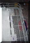
The turret got most of the modifications. I’ll start with the back. In
the rear turret basket are tiny slots in the solid portion towards the top.
These were made with the smallest drill bit I have. A pencil line marked where
these would be, and then I drilled numerous holes on that line. The leftover
plastic was scraped with a dental tool and an Exacto knife until nice little
slots were made.
The crosswind sensor in the kit was wrong for the M1 I was modeling, so Gary
gave me one from the Tamiya kit that he was not using. The middle of the sensor
is hollow (to allow the wind to go through), so mine was hollowed out and a thin
piece of plastic inserted to make two channels. A strap for the sensor was made
from lead foil and copper wire.
The antennas were next. The actual antenna springs have a bulge in the middle
of them. This was accomplished by stretching plastic tubing over a candle to
make it narrower, then using an Emory board to make a cone shape at one end.
Then, cut the tube the correct length and sand the other side cone shaped,
making two ice-cream cones, top to top with a hole in the middle. One of them
got a piece of brass tubing and the other got a piece of brass rod inserted,
then steel wire (available at Hobby Lobby in various diameters) was wound around
the ice cream cones. Make two. On the M1 I am modeling, there is only one
antenna, which was made from thin brass wire and inserted into the brass tubing.
The last thing before leaving the rear basket is to attach small steel loops
on the bottom. These were used to hang ball and chain early detonation devices
much like on the Merkava. I don’t know if they were ever used, but they are
there. If I ever saw an M1 at a model show or in real life with them, that would
certainly draw my attention.
The blast panels on top and at the rear of the turret do not have the little
discs on them, so Testors liquid cement and putty was applied and then stippled
with a stiff brush to match the rest of the blast panels.
The metal rods covering the side storage bins in the kit and in the FSM
article are wrong for this model. There is an additional endplate towards the
rear of the turret where the metal rods end right next to the rear turret
basket. The Tamiya kit has it right. A small oval shaped disc was created from
styrene for the new endplate. The old endplate on the kit had holes drilled in
it so the brass rod could go through it and end at the new end plate. I know
this is not right, but I then bent the brass rods inwards so it would roughly
align with the rear turret basket.
Moving further forward, the smoke grenade launcher was wired with lead wire
and a small triangular piece of styrene was built to extend the conduit outward
from the edge of the turret to protect the wire. Various grab handles were
placed on the front of the side turret storage bins made from steel wire. Also,
attachment points were made for the side storage bins and smoke grenade holders
made from styrene and detailed with Grantline bolts.
The tube for the coaxial machine gun (the one next to the main gun) was
replaced with a brass tube. Inside the tube, there are "fins." I replicated
these by gluing small pieces of steel wire around the tube, and then snipping
off the parts that hung out. I do not know what the fins are, maybe cooling fins
or strengthening devices. Also, the lifting lugs for the gun have holes in them,
so mine got the same treatment.
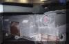
The M1 at the Armory was used in Desert Storm and after the war, it was
rigged up with devices to play military "laser tag." The devices were attached
to the vehicle with Velcro strips. This was replicated with thin strips of
masking tape. The Velcro on the right side of the turret has been stripped off,
revealing the Desert Storm paint scheme underneath. The strip continues along
the rear turret basket and onto the left side running just under the side
storage bins and wrapping around to the front of the vehicle.
Two modifications were made to the commander’s copula. There is a small
rectangular piece of metal on the front of the cupola ring. This was made with
styrene and detailed with a Grantline bolt. The other modification was two small
lifting rings were attached to the left and right side of the cupola ring. The
.50 cal MG was wired, also.
On the right side of the turret, near the bottom front is a casting number
made with a weld bead of "5269." This was replicated by using part numbers from
the part trees. They were cut off using a chisel blade and then glued in place.
Painting
The places where the Desert Storm paint shows through was painted first.
The area on the turret side was then masked with masking tape and the spots on
the turret front and turret top were masked with masking solution. The tank was
spayed is current green color right over the Desert Storm paint scheme. The
smoke dischargers had a canvas cover over them when painted green, so they are
still their original color. After the Desert Storm acrylic color was applied, a
coat of flat clear lacquer was applied. Over this, a coat of dark green acrylic
was applied. The masks were carefully peeled off to reveal the Desert Storm
color underneath. The side where the Velcro was peeled off was stained with oil
colors to represent what I believe is where the Velcro was peeled off (or fell
off) and the glue residue attracted dirt and other lovely, yucky stuff.
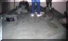
The bogies were first painted gray and then using a circular drafting
template to mask the gray rubber part, the center was painted dark green.
Additional parts of the turret were painted such as the inside of the gun
barrel, laser sighting on the tip of the barrel, front of the smoke discharges,
top of the cross wind sensor, antennas and other parts. The "T 37" are Archer
Dry Transfers. Another coat of flat clear lacquer was applied over this to
prepare for further weathering.
Due to the almost chalky appearance of the real deal, the model was given a
wash of rubbing alcohol and white pastel dust, concentrating mostly on the
horizontal surfaces. This was then wiped with a t-shirt dapped in alcohol until
the finish was as I wanted it. The wheels were placed on a Shiskabob skewer in
the Dremel with a dab of alcohol with more of a dirt colored pastel. Turn it on
and watch it fly and dry. The only washes on the model are the oil stains
scattered all over and there was not any dry-brushing done except the vents,
which are invisible under the turret.
Tracks
Let me just say a few words about the kit tracks- They Suck! If you like
mean, nasty, ejector pin marks (each individual link had 2!) then have at it. I
super glued each hole, and then scraped each one. When you get the links to go
around the sprocket, bend each end connector down with your tweezers or else
they’ll look like they shoot up into outer space. While you’re on the end
connectors, drill two small holes with your Exacto knife blade to simulate the
track pins.
The painting followed as such: first a coat of dirt colored paint was
applied. After that, a wash of burnt sienna. Over that, a not-so-dry drybrush of
the same burnt sienna oil paint was applied, more or less smearing the paint on.
This was then lightened up and put on the outside of the track pads. While this
was still wet, white pastel dust was dabbed on. The inside rubber track pads
were painted dark gray and then received some light gray pastel. The inside part
of each end connector was painted silver along with each guide horn to show
areas of high wear.
After all that work, the tracks came out looking pretty good, if I do say so
myself.
Final Assembly
Due to the warpage of the hull, I knew we had a problem. If the turret ever
came off the hull, it would never fit back on. I could have built some sort of
support for the hull top, but I opted to just glue the turret in one place.
After this was glued, the hull was glued to the chassis. I would not recommend
this method since the model was already painted and there were seams to patch
up, sand, and then repaint and reweather. Finally, the antennae was properly
bent and attached
A simple base was made and the model was bolted to the base just like the one
in FSM. Gary supplied the unit pins and they were inserted into predrilled holes
in the base.
There you have it, a much improved model built in a realistic manor, and
ready for action!
|