|
Building the Model Airways 1/16th Scale Sopwith Camel
Partial Kit 1 of 8
The Basic Fuselage
Kit one arrived in the mail and upon examining the contents,
I was once again wondering what I was thinking.
What I have here is a small sheet of laser cut wood parts, a
bunch of 3/32" and 1/8" sq. stringers, some white metal details, the previously
mentioned tools, and a set of plans.
A trip to the local Michaels crafts shop added some extra
wood pieces for the jigs and a large foam board to build this thing on, plus a
bunch of push pins.
I took wood shop in jr. high (yes, it was still called jr.
high when I went there - I'm old), but I won't claim I was good at it. I did
build some of the old Guillow's balsa airplane kits as a kid, so I have at least
glued pieces of wood together before. Still, this is the big leagues so we'll
have to see if general modeling skills are of any use at all.
After reading through the kit instructions and examining the
plans carefully, I've decided I just might be able to pull this off.
Let's get started
I started by laying out the plan for Jig4 on the foam board
and covering it with wax paper then pinning the whole thing in place. Since the
sides are built flat, I just pinned the lasercut parts in place on the plan, cut
the stringers to the right length and started gluing things in place using lots
of staightpins to hold it all in place while the glue dried.
The two sides are identical other than the engine mounts.
Each mount has lightening holes carved in one side and these must face outward.
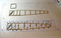
Here is the right side in place on the plans. The finished
left side is above it. The rectangular piece at the top is the front frame.
Once the sides are done, I used the Jig5 plan and pinned some
wood pieces to the foam board to help in assembling the two sides. Each side is
glued to the front frame then stringers are cut to length and glued to the
appropriate positions on each side.
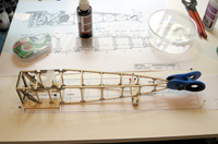
Here are the sides in place on the jig. the cross pieces are
attached and a clamp holds the tail together while the glue drys
Once the fuselage box is done, the lasercut parts for the
fuelage back are added along with those stringers. The cockpit framework, which
consists of some whitemetal parts and some more 3/32" stringers is installed
next. Then a bunch of eyelets that will be used for rigging have to glued in
place along with the front machine gun mount.
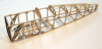
Here's the finished kit 1 before staining.
OK. I've survived, but this is really different from plastic
modeling. Other than the few laser cut pieces and the metal parts, everthing has
to be measured and cut. That's not too hard, though. The real difference I
noticed is that there are no locating pins or guides. You have to position
everything precisely without any help besides the plans. Each fuselage side has
to be identical or the crossbeams won't line up properly. If the machinegun mount
is in the wrong place, then the guns won't mount properly later.
Still, being an experienced modeler is a big help with
seemingly simple things like getting the right amount of glue in the right
places and not gluing my fingers together with the superglue used on the metal
parts.
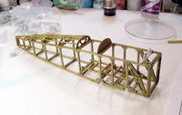
Here's the finished part after staining with the English Oak wood
stain that comes with the kit and a nice glossy varnish.
So far so good. On to Step2.
STEP 2 - Finishing the fuselage
|